

A More Intimate Look at The Core Parameters of Tape Delay
Tape delay is built on a set of five primary parameters that define how time-domain effects behave and sound:
- Delay time
- Feedback
- Modulation speed
- Modulation width
- High-frequency decay
Each parameter shapes how audio is repeated, altered, and degraded over time. Together, they explain not only how tape delay works, but why it sounds the way it does—organic, evolving, and increasingly distant with each repeat.
Time-domain effects are not static processes; they are systems in motion, shaped by mechanical, electrical, and acoustic limitations.
Delay Time: Creating the Initial Echo
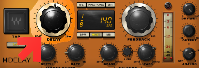
How Delay Time Is Generated
The first parameter of time-domain effects is delay time.
In a tape delay system, delay time is created by placing the tape recorder into record mode, allowing recording to begin.
A critical requirement is that the recorder must be set to monitor the delayed recorded signal from the reproduction head, rather than operating in input monitor mode. This distinction ensures that what is heard is the delayed signal, not the original input.
The Signal Path Through the Tape Machine
The process unfolds in a clear sequence:
- The first-generation copied signal enters the tape machine.
- It travels to the record head, where it is written onto tape.
- The tape moves physically to the reproduction head.
- The reproduction head replays the signal.
- The output is sent back to the return channel on the mixer.
This physical distance between heads, combined with tape speed, defines the delay.
Controlling Delay Time with Tape Speed
Delay time is adjusted by changing the speed of the tape using a varispeed control.
This control may also be labeled as:
- Speed
- Pitch control
Changing tape speed directly alters how long it takes for the signal to travel from the record head to the reproduction head, thereby increasing or decreasing delay time.
Feedback: Building Repeating Echoes
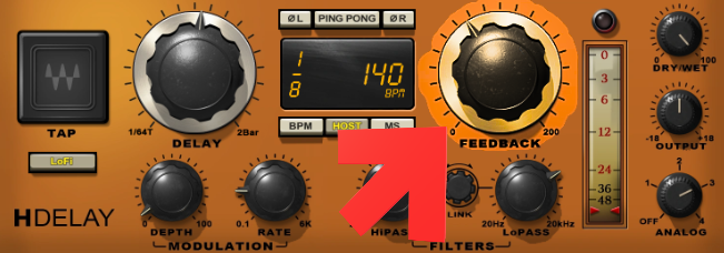
What Feedback Really Does
The second parameter is feedback.
Feedback is achieved by creating a second-generation copy of the first delayed signal and sending it back to the record head again.
This is accomplished by:
- Using the same auxiliary send button on the return channel
- That is already used on the original source input channel
Each pass through the tape creates a new generation of the signal.
Why Each Repeat Loses Quality
With every new generation copy, some quality is lost. This loss is caused by:
- Electromagnetic inefficiencies
- Mechanical limitations of tape recording
The most noticeable degradation occurs in the high frequencies.
Every repeat carries less detail than the one before it.
This behavior closely mirrors how echoes behave in real acoustic spaces.
Modulation: Movement in Time and Pitch
Introducing Modulation Through Varispeed
To create a modulated effect, the tape recorder’s speed control must be rotated backward and forward continuously for as long as modulation is desired.
This motion introduces:
- Variations in delay time
- Variations in pitch
Pitch Changes Explained
The direction of speed change determines pitch behavior:
- If tape speed is increased after recording but before playback, the pitch rises
- If tape speed is decreased, the pitch falls
These fluctuations are an essential part of classic tape-based modulation effects.
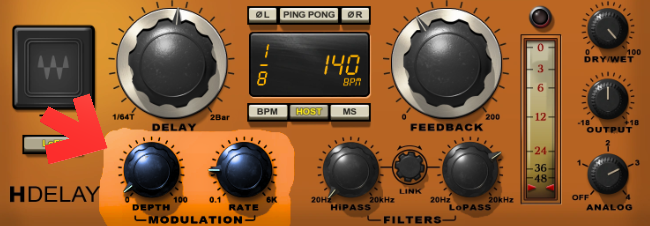
Modulation Speed: Rate of Movement
From Manual Control to Automation
In traditional tape systems, modulation speed depended entirely on how fast the varispeed control was moved by hand.
In contrast, modern systems—whether solid-state analog, digital hardware, or software delay plugins—use a programmable LFO (Low-Frequency Oscillator) to simulate this movement.
The LFO generates a modulating control signal that adjusts:
- Pitch
- Delay time
Understanding Modulation Speed
Modulation speed is determined by how quickly the varispeed control is rotated.
This parameter may also be referred to as:
- Modulation rate
- Modulation frequency
Different speed settings produce distinct effects:
- Slow speeds result in subtle phasing
- Fast speeds create deep flanging
Modulation Width: Depth and Intensity
How Wide the Modulation Goes
While modulation speed defines how fast changes occur, modulation width defines how far they go.
It is determined by:
- The degree of rotation of the varispeed control
Greater rotation produces:
- Deeper pitch variation
- More pronounced delay modulation
Alternate Terminology
Modulation width may also be labeled as:
- Modulation intensity
- Modulation depth
- Modulation amount
These terms all describe the same concept: the range of variation applied to the signal.
High-Frequency Decay: Why Echoes Grow Duller
Acoustic Behavior in Real Spaces
When sound reflects within a space such as a room:
- High frequencies are absorbed faster
- Low frequencies persist longer
As a result, echoes become progressively duller over time.
Tape Delay as a Natural Emulator
The tape recording process naturally mimics this behavior. Each time a sound is:
- Recorded to tape
- Played back
- Fed back to be recorded again
High harmonic frequencies decay more rapidly than low frequencies.
This effect arises from the electromechanical inefficiencies of tape recording and is a defining characteristic of tape delay.
Tape delay does not merely repeat sound—it reshapes it.
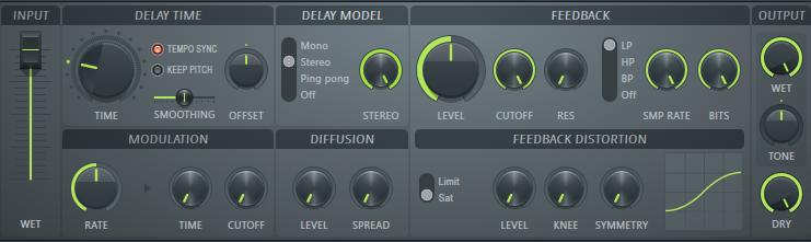
Digital Delay and High-Frequency Control
Why Digital Delays Sound Different
Digital delay lines operate by:
- Sampling a source signal
- Replaying it repeatedly according to the feedback setting
Because this process does not inherently degrade the signal, digital repeats do not naturally deteriorate in quality.
Simulating Tape and Natural Echoes
To recreate the behavior of tape and acoustic spaces, digital delay systems typically include:
- A low-pass filter
- Or high-cut filter
This filter is applied to the repeated signal to simulate high-frequency decay.
Alternate Names for High-Frequency Decay
High-frequency decay is also known as:
- High-frequency damping
- High cut
These controls restore the natural loss of brightness that occurs in real-world echoes and tape-based systems.